本文转自:https://www.cisco.com/c/en/us/td/docs/security/asa/asa98/configuration/vpn/asa-98-vpn-config/vpn-params.html
Chapter: General VPN Parameters
Chapter Contents
The ASA implementation of virtual private networking includes useful features that do not fit neatly into categories. This chapter describes some of these features.
- Guidelines and Limitations
- Configure IPsec to Bypass ACLs
- Permitting Intra-Interface Traffic (Hairpinning)
- Setting Maximum Active IPsec or SSL VPN Sessions
- Use Client Update to Ensure Acceptable IPsec Client Revision Levels
- Implement NAT-Assigned IP to Public IP Connection
- Configure VPN Session Limits
- Using an Identify Certificate When Negotiating
- Configure the Pool of Cryptographic Cores
- Configure Dynamic Split Tunneling
- Viewing Active VPN Sessions
- About ISE Policy Enforcement
- Configure Advanced SSL Settings
- Persistent IPsec Tunneled Flows
Guidelines and Limitations
This section includes the guidelines and limitations for this feature.
Context Mode Guidelines
Supported in single and multiple context mode. In the appropriate release of the ASA General Operations CLI Configuration Guide, refer to Guidelines for Multiple Context Mode for the list of what is not supported in multiple context mode, and New Features which gives the breakdown of what was added throughout the releases.
Firewall Mode Guidelines
Supported only in routed firewall mode. Transparent mode is not supported.
Configure IPsec to Bypass ACLs
To permit any packets that come from an IPsec tunnel without checking ACLs for the source and destination interfaces, enter the sysopt connection permit-vpn command in global configuration mode.
You might want to bypass interface ACLs for IPsec traffic if you use a separate VPN concentrator behind the ASA and want to maximize the ASA performance. Typically, you create an ACL that permits IPsec packets by using the access-list command and apply it to the source interface. Using an ACL allows you to specify the exact traffic you want to allow through the ASA.
The following example enables IPsec traffic through the ASA without checking ACLs:
hostname(config)# sysopt connection permit-vpn
 Note Note | Decrypted through-traffic is permitted from the client despite having an access group on the outside interface, which calls a deny ip any any ACL, while no sysopt connection permit-vpn is configured.Trying to control access to the protected network via site-to-site or remote access VPN using the no sysopt permit-vpn command in conjunction with an access control list (ACL) on the outside interface are not successful.sysopt connection permit-vpn will bypass ACLs (both in and out) on interface where crypto map for that interesting traffic is enabled, along with egress (out) ACLs of all other interfaces, but not the ingress (in) ACLs.In this situation, when management-access inside is enabled, the ACL is not applied, and users can still connect to the ASA using SSH. Traffic to hosts on the inside network is blocked correctly by the ACL, but decrypted through-traffic to the inside interface is not blocked.The ssh and http commands are of a higher priority than the ACLs. To deny SSH, Telnet, or ICMP traffic to the box from the VPN session, use ssh, telnet and icmpcommands. |
Permitting Intra-Interface Traffic (Hairpinning)
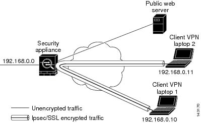
The ASA includes a feature that lets a VPN client send IPsec-protected traffic to another VPN user by allowing that traffic in and out of the same interface. This is also called “hairpinning”, which can be thought of as VPN spokes (clients) connecting through a VPN hub (the ASA).
Hairpinning can also redirect incoming VPN traffic back out through the same interface as unencrypted traffic. This can be useful, for example, to a VPN client that does not have split tunneling, but needs to both access a VPN and browse the web.
The figure below shows VPN Client 1 sending secure IPsec traffic to VPN Client 2 while also sending unencrypted traffic to a public web server.
To configure this feature, use the same-security-traffic command in global configuration mode with its intra-interface argument.
The command syntax is same-security-traffic permit {inter-interface | intra-interface}.
The following example shows how to enable intra-interface traffic:
hostname(config)# same-security-traffic permit intra-interface
hostname(config)#
| Note | Use the same-security-traffic command with the inter-interface argument to permit communication between interfaces with the same security level. This feature is not specific to IPsec connections. For more information, see the “Configuring Interface Parameters” chapter of this guide. |
To use hairpinning, you must apply the proper NAT rules to the ASA interface, as described in NAT Considerations for Intra-Interface Traffic.
NAT Considerations for Intra-Interface Traffic
For the ASA to send unencrypted traffic back out through the interface, you must enable NAT for the interface so that publicly routable addresses replace your private IP addresses (unless you already use public IP addresses in your local IP address pool). The following example applies an interface PAT rule to traffic sourced from the client IP pool:
hostname(config)# ip local pool clientpool 192.168.0.10-192.168.0.100
hostname(config)# object network vpn_nat
hostname(config-network-object)# subnet 192.168.0.0 255.255.255.0
hostname(config-network-object)# nat (outside,outside) interface
When the ASA sends encrypted VPN traffic back out this same interface, however, NAT is optional. The VPN-to-VPN hairpinning works with or without NAT. To apply NAT to all outgoing traffic, implement only the commands above. To exempt the VPN-to-VPN traffic from NAT, add commands (to the example above) that implement NAT exemption for VPN-to-VPN traffic, such as:
hostname(config)# nat (outside,outside) source static vpn_nat vpn_nat destination static vpn_nat vpn_nat
For more information on NAT rules, see the “Applying NAT” chapter of this guide.
Setting Maximum Active IPsec or SSL VPN Sessions
To limit VPN sessions to a lower value than the ASA allows, enter the vpn-sessiondbcommand in global configuration mode:
vpn-sessiondb {max-anyconnect-premium-or-essentials-limit <number> | max-other-vpn-limit <number>}
The max-anyconnect-premium-or-essentials-limit keyword specifies the maximum number of AnyConnect sessions, from 1 to the maximum sessions allowed by the license.
| Note | The correct licensing, term, tier, and user count is no longer determined with these commands. Refer to the AnyConnect Ordering Guide: http://www.cisco.com/c/dam/en/us/products/collateral/security/anyconnect-og.pdf |
The max-other-vpn-limit keyword specifies the maximum number of VPN sessions other than AnyConnect client sessions, from 1 to the maximum sessions allowed by the license. This includes the Cisco VPN client (IPsec IKEv1) and Lan-to-Lan VPN sessions.
This limit affects the calculated load percentage for VPN Load Balancing.
The following example shows how to set a maximum Anyconnect VPN session limit of 450:
hostname(config)# vpn-sessiondb max-anyconnect-premium-or-essentials-limit 450
hostname(config)#
Use Client Update to Ensure Acceptable IPsec Client Revision Levels
| Note | The information in this section applies to IPsec connections only. |
The client update feature lets administrators at a central location automatically notify VPN client users that it is time to update the VPN client software.
Remote users might be using outdated VPN software or hardware client versions. You can use the client-update command at any time to enable updating client revisions; specify the types and revision numbers of clients to which the update applies; provide a URL or IP address from which to get the update; and, in the case of Windows clients, optionally notify users that they should update their VPN client version. For Windows clients, you can provide a mechanism for users to accomplish that update. This command applies only to the IPsec remote-access tunnel-group type.
To perform a client update, enter the client-update command in either general configuration mode or tunnel-group ipsec-attributes configuration mode. If the client is already running a software version on the list of revision numbers, it does not need to update its software. If the client is not running a software version on the list, it should update. The following procedure explains how to perform a client update:
Procedure
| Step 1 | In global configuration mode, enable client update by entering this command: hostname(config)# client-update enable hostname(config)# |
| Step 2 | In global configuration mode, specify the parameters for the client update that you want to apply to all clients of a particular type. That is, specify the type of client, the URL or IP address from which to get the updated image, and the acceptable revision number or numbers for that client. You can specify up to four revision numbers, separated by commas.If the user’s client revision number matches one of the specified revision numbers, there is no need to update the client. This command specifies the client update values for all clients of the specified type across the entire ASA.Use this syntax: hostname(config)# client-update type type url url-string rev-nums rev-numbers hostname(config)# The available client types are win9X (includes Windows 95, Windows 98 and Windows ME platforms), winnt (includes Windows NT 4.0, Windows 2000 and Windows XP platforms), windows (includes all Windows based platforms).If the client is already running a software version on the list of revision numbers, it does not need to update its software. If the client is not running a software version on the list, it should update. You can specify up to three of these client update entries. The keyword windows covers all of the allowable Windows platforms. If you specify windows , do not specify the individual Windows client types.Note For all Windows clients, you must use the protocol http:// or https:// as the prefix for the URL.The following example configures client update parameters for the remote access tunnel group. It designates the revision number 4.6.1 and the URL for retrieving the update, which is https://support/updates. hostname(config)# client-update type windows url https://support/updates/ rev-nums 4.6.1 hostname(config)# Alternatively, you can configure client update just for individual tunnel groups, rather than for all clients of a particular type. (See Step 3.)Note You can have the browser automatically start an application by including the application name at the end of the URL; for example: https://support/updates/vpnclient.exe. |
| Step 3 | Define a set of client-update parameters for a particular ipsec-ra tunnel group.In tunnel-group ipsec-attributes mode, specify the tunnel group name and its type, the URL or IP address from which to get the updated image, and a revision number. If the user’s client’s revision number matches one of the specified revision numbers, there is no need to update the client, for example, for a Windows client enter this command: hostname(config)# tunnel-group remotegrp type ipsec-ra hostname(config)# tunnel-group remotegrp ipsec-attributes hostname(config-tunnel-ipsec)# client-update type windows url https://support/updates/ rev-nums 4.6.1 hostname(config-tunnel-ipsec)# |
| Step 4 | (Optional) Send a notice to active users with outdated Windows clients that their client needs updating. For these users, a pop-up window appears, offering them the opportunity to launch a browser and download the updated software from the site that you specified in the URL. The only part of this message that you can configure is the URL. (See Step 2 or 3.) Users who are not active get a notification message the next time they log on. You can send this notice to all active clients on all tunnel groups, or you can send it to clients on a particular tunnel group. For example, to notify all active clients on all tunnel groups, enter the following command in privileged EXEC mode: hostname# client-update all hostname# If the user’s client’s revision number matches one of the specified revision numbers, there is no need to update the client, and no notification message is sent to the user. |
What to do next
| Note | If you specify the client-update type as windows (specifying all Windows-based platforms) and later want to enter a client-update type of win9x or winnt for the same entity, you must first remove the windows client type with the no form of the command, then use new client-update commands to specify the new client types. |
Implement NAT-Assigned IP to Public IP Connection
In rare situations, you might want to use a VPN peer’s real IP address on the inside network instead of an assigned local IP address. Normally with VPN, the peer is given an assigned local IP address to access the inside network. However, you might want to translate the local IP address back to the peer-s real public address if, for example, your inside servers and network security is based on the peer’s real IP address.
Cisco ASA 55xx introduced a way to translate the VPN client’s assigned IP address on the internal/protected network to its public (source) IP address. This feature supports the scenario where the target servers/services on the internal network and network security policy require communication with the VPN client’s public/source IP instead of the assigned IP on the internal corporate network.
You can enable this feature on one interface per tunnel group. Object NAT rules are dynamically added and deleted when the VPN session is established or disconnected.
Because of routing issues, we do not recommend using this feature unless you know you need it.
- Only supports legacy (IKEv1) and AnyConnect clients.
- Return traffic to the public IP addresses must be routed back to the ASA so the NAT policy and VPN policy can be applied.
- Only supports IPv4 assigned and public addresses.
- Multiple peers behind a NAT/PAT device are not supported.
- Does not support load balancing (because of routing issue).
- Does not support roaming.
Procedure
| Step 1 | In global configuration mode, enter tunnel general. |
| Step 2 | Use this syntax to enable the address translation: hostname(config-tunnel-general)# nat-assigned-to-public-ip interface
This command dynamically installs NAT policies of the assigned IP address to the public IP address of the source. The interface determines where to apply NAT. |
| Step 3 | Use this syntax to disable the address translation: hostname(config-tunnel-general)# no nat-assigned-to-public-ip |
Displaying VPN NAT Policies
Address translation uses the underlying object NAT mechanisms; therefore, the VPN NAT policy displays just like manually configured object NAT policies. This example uses 95.1.226.4 as the assigned IP and 75.1.224.21 as the peer’s public IP:
hostname# show nat
Auto NAT Policies (Section 2)
1 (outside) to (inside) source static _vpn_nat_95.1.226.4 75.1.224.21
    translate_hits = 315, untranslate_hits = 315

prompt# show nat detail

Auto NAT Policies (Section 2)
1 (outside) to (inside) source static _vpn_nat_95.1.226.4 75.1.224.21
    translate_hits = 315, untranslate_hits = 315
    Source - Origin: 95.1.226.4/32, Translated: 75.1.224.21/32
Outside is the interface to which the AnyConnect client connects and inside is the interface specific to the new tunnel group.
| Note | Since VPN NAT policies are dynamic and not added to the configuration, the VPN NAT object and NAT policy are hidden from the show run object and show run nat reports. |
Configure VPN Session Limits
You can run as many IPsec and SSL VPN sessions as your platform and ASA license supports. To view the licensing information including maximum sessions for your ASA, enter the show version command in global configuration mode and look for the licensing section. The following example shows the command and the licensing information from the output of this command; the other output is redacted for clarity.
hostname(config)# show version
...
Licensed features for this platform:
Maximum Physical Interfaces       : Unlimited      perpetual
Maximum VLANs                     : 500            perpetual
Inside Hosts                      : Unlimited      perpetual
Failover                          : Active/Active  perpetual
Encryption-DES                    : Enabled        perpetual
Encryption-3DES-AES               : Enabled        perpetual
Security Contexts                 : 100            perpetual
Carrier                           : Enabled        perpetual
AnyConnect Premium Peers          : 5000           perpetual
AnyConnect Essentials             : 5000           perpetual
Other VPN Peers                   : 5000           perpetual
Total VPN Peers                   : 5000           perpetual
AnyConnect for Mobile             : Enabled        perpetual
AnyConnect for Cisco VPN Phone    : Enabled        perpetual
Advanced Endpoint Assessment      : Enabled        perpetual
Shared License                    : Disabled       perpetual
Total TLS Proxy Sessions          : 3000           perpetual
Botnet Traffic Filter             : Disabled       perpetual
IPS Module                        : Disabled       perpetual
Cluster                           : Enabled        perpetual
Cluster Members                   : 2              perpetual

This platform has an ASA5555 VPN Premium license.
Show License Resource Allocation
Use the following command to show the resource allocation:
asa2(config)# sh resource allocation
Resource							Total				% of Avail
Conns[rate]				100(U)						0.00%
Inspects[rate]	unlimited
Syslogs[rate]		unlimited
Conns										unlimited
Hosts										unlimited
IPsec										unlimited
Mac-addresses		unlimited
ASDM											10										5.00%
SSH												10										10.00%
Telnet									10										10.0%
Xlates									unlimited
AnyConnect					1000								10%
AnyConnectBurst	200								2%
OtherVPN							2000								20%
OtherVPNBurst		1000								10%
Show License Resource Usage
Use the following command to show resource usage:
| Note | You can also use the sh resource usage system controller all 0 command to show system level usage with the limit as the platform limit.ASA(config-ca-trustpoint)# sh resource usage Resource Current Peak Limit Denied Context Conns 1 16 280000 0 System Hosts 2 10 N/A 0 System AnyConnect 2 25 1000 0 cust1 AnyConnectBurst 0 0 200 0 cust1 OtherVPN 1 1 2000 0 cust2 OtherVPNBurst 0 0 1000 0 cust2 |
Limit VPN Sessions
To limit AnyConnect VPN sessions (either IPsec/IKEv2 or SSL) to a lower value than the ASA allows, use the vpn-sessiondb max-anyconnect-premium-or-essentials-limit command in global configuration mode. To remove the session limit, use the no version of this command.
If the ASA license allows 500 SSL VPN sessions, and you want to limit the number of AnyConnect VPN sessions to 250, enter the following command:
hostname(config)# vpn-sessiondb max-anyconnect-premium-or-essentials-limit 250
hostname(config)#
To remove the session limit, use the no version of this command.:
hostname(config)# no vpn-sessiondb max-anyconnect-premium-or-essentials-limit 250
hostname(config)#
Using an Identify Certificate When Negotiating
The ASA needs to use an identity certificate when negotiating the IKEv2 tunnel with AnyConnect clients. For ikev2 remote access trustpoint configuration, use the following commands
crypto ikev2 remote-access trustpoint <name> [line<number>]
Using this command allows the AnyConnect client to support group selection for the end user. You can configure two trustpoints at the same time: two RSA, two ECDSA, or one of each. The ASA scans the configured trustpoint list and chooses the first one that the client supports. If ECDSA is preferred, you should configure that trustpoint before the RSA trustpoint.
The line number option specifies where in the line number you want the trustpoint inserted. Typically, this option is used to insert a trustpoint at the top without removing and re-adding the other line. If a line is not specified, the ASA adds the trustpoint at the end of the list.
If you try to add a trustpoint that already exists, you receive an error. If you use the no crypto ikev2 remote-access trustpoint command without specifying which trustpoint name to remove, all trustpoint configuration is removed.
Configure the Pool of Cryptographic Cores
You can change the allocation of cryptographic cores on Symmetric Multi-Processing (SMP) platforms to increase the throughput of AnyConnect TLS/DTLS traffic. These changes can accelerate the SSL VPN datapath and provide customer-visible performance gains in AnyConnect, smart tunnels, and port forwarding. These steps describe configuring the pool of cryptographic cores in either single or multiple context mode.
Cryptographic core re-balancing is available on the following platforms:
- 5585-X
- 5545-X
- 5555-X
- ASASM
Procedure
Specify how to allocate crypto accelerator processors:crypto engine accelerator-biasbalanced—Equally distributes cryptography hardware resources (Admin/SSL and IPsec cores).ipsec—Allocates cryptography hardware resources to favor IPsec (includes SRTP encrypted voice traffic).ssl—Allocates cryptography hardware resources to favor Admin/SSL.Example: hostname(config)# crypto engine ? configure mode commands/options: accelerator-bias
Specify how to allocate crypto accelerator processors hostname(config)# crypto engine accelerator-bias ? configure mode commands/options balanced - Equally distribute crypto hardware resources ipsec - Allocate crypto hardware resources to favor IPsec/Encrypted Voice (SRTP) ssl - Allocate crypto hardware resources to favor SSL hostname(config)# crypto engine accelerator-bias ssl
|
Configure Dynamic Split Tunneling
With dynamic split tunneling, you can dynamically provision split exclude tunneling after tunnel establishment based on the host DNS domain name. Dynamic split tunneling is configured by creating a custom attribute and adding it to a group policy.
Before you begin
To use this feature, you must have AnyConnect release 4.5 (or later). Refer to About Dynamic Split Tunneling for further explanation.
Procedure
| Command or Action | Purpose | |
|---|---|---|
| Step 1 | Define the custom attribute type in the WebVPN context with the following command:anyconnect-custom-attr dynamic-split-exclude-domains description dynamic split exclude domains | |
| Step 2 | Define the custom attribute names for each cloud/web service that needs access by the client outside the VPN tunnel. For example, add Google_domains to represent a list of DNS domain names pertaining to Google web services. The attribute value contains the list of domain names to exclude from the VPN tunnel and must be comma-separated-values (CSV) format as the following: anyconnect-custom-data dynamic-split-exclude-domains webex.com, webexconnect.com, tags.tiqcdn.com | |
| Step 3 | Attach the previously defined custom attribute to a certain policy group with the following command, executed in the group-policy attributes context: anyconnect-custom dynamic-split-exclude-domains value webex_service_domains |
What to do next
If split include tunneling is configured, a dynamic split exclusion is enforced only if at least one of the DNS response IP addresses is part of the split-include network. If there is no overlap between any of the DNS response IP addresses and any of the split-include networks, enforcing dynamic split exclusion is not necessary since traffic matching all DNS response IP addresses is already excluded from tunneling.
Viewing Active VPN Sessions
The following topics explain how to view VPN session information.
- Viewing Active AnyConnect Sessions by IP Address Type
- Viewing Active Clientless SSL VPN Sessions by IP Address Type
- Viewing Active LAN to LAN VPN Sessions by IP Address Type
Viewing Active AnyConnect Sessions by IP Address Type
To view active AnyConnect sessions using the command line interface, enter the show vpn-sessiondb anyconnect filter p-ipversion or show vpn-sessiondb anyconnect filter a-ipversion command in privileged EXEC mode.
- Display the active AnyConnect sessions which are filtered by the endpoint’s public IPv4 or IPv6 address. The public address is the address assigned to the endpoint by the enterprise.
show vpn-sessiondb anyconnect filter p-ipversion {v4 | v6} - Display the active AnyConnect sessions which are filtered by the endpoint’s assigned IPv4 or IPv6 address. The assigned address is the address assigned to the AnyConnect Secure Mobility Client by the ASA.
show vpn-sessiondb anyconnect filter a-ipversion {v4 | v6}
Example Output from show vpn-sessiondb anyconnect filter p-ipversion [v4 | v6] command
hostname(config)# show vpn-sessiondb anyconnect filter p-ipversion v4

Session Type: AnyConnect

Username     : user1                  Index        : 40
Assigned IP  : 192.168.17.10          Public IP    : 198.51.100.1
Protocol     : AnyConnect-Parent SSL-Tunnel
License      : AnyConnect Premium
Encryption   : AnyConnect-Parent: (1)none  SSL-Tunnel: (1)RC4
Hashing      : AnyConnect-Parent: (1)none  SSL-Tunnel: (1)SHA1
Bytes Tx     : 10570                  Bytes Rx     : 8085
Group Policy : GroupPolicy_SSLACCLIENT
Tunnel Group : SSLACCLIENT
Login Time   : 15:17:12 UTC Mon Oct 22 2012
Duration     : 0h:00m:09s
Inactivity   : 0h:00m:00s
NAC Result   : Unknown
VLAN Mapping : N/A                    VLAN         : none
Output from show vpn-sessiondb anyconnect filter a-ipversion [v4 | v6] command
hostname(config)# show vpn-sessiondb anyconnect filter a-ipversion v6

Session Type: AnyConnect

Username     : user1                  Index        : 45
Assigned IP  : 192.168.17.10
Public IP    : 2001:DB8:8:1:90eb:3fe5:9eea:fb29
Assigned IPv6: 2001:DB8:9:1::24
Protocol     : AnyConnect-Parent SSL-Tunnel
License      : AnyConnect Premium
Encryption   : AnyConnect-Parent: (1)none  SSL-Tunnel: (1)RC4
Hashing      : AnyConnect-Parent: (1)none  SSL-Tunnel: (1)SHA1
Bytes Tx     : 10662                  Bytes Rx     : 17248
Group Policy : GroupPolicy_SSL_IPv6   Tunnel Group : SSL_IPv6
Login Time   : 17:42:42 UTC Mon Oct 22 2012
Duration     : 0h:00m:33s
Inactivity   : 0h:00m:00s
NAC Result   : Unknown
VLAN Mapping : N/A                    VLAN         : none
Viewing Active Clientless SSL VPN Sessions by IP Address Type
To view active clientless SSL VPN sessions using the command line interface, enter the show vpn-sessiondb webvpn filter ipversion command in privileged EXEC mode.
The public address is the address assigned to the endpoint by the enterprise.
show vpn-sessiondb webvpn filter ipversion {v4 | v6}
Examples
hostname# sh vpn-sessiondb webvpn filter ipversion v4

Session Type: WebVPN

Username     : user1                  Index        : 63
Public IP    : 171.16.17.6
Protocol     : Clientless
License      : AnyConnect Premium
Encryption   : Clientless: (1)RC4     Hashing      : Clientless: (1)SHA1
Bytes Tx     : 62454                  Bytes Rx     : 13082
Group Policy : SSLv6                  Tunnel Group : SSL_IPv6
Login Time   : 18:07:48 UTC Mon Oct 22 2012
Duration     : 0h:00m:16s
Inactivity   : 0h:00m:00s
NAC Result   : Unknown
VLAN Mapping : N/A                    VLAN         : none
Viewing Active LAN to LAN VPN Sessions by IP Address Type
To view active clientless SSL VPN sessions using the command line interface, enter the show vpn-sessiondb l2l filter ipversion command in privileged EXEC mode.
This command shows active lan to lan VPN sessions filtered by the connection’s public IPv4 or IPv6 address.
The public address is the address assigned to the endpoint by the enterprise.
show vpn-sessiondb l2l filter ipversion {v4 | v6}
About ISE Policy Enforcement
The Cisco Identity Services Engine (ISE) is a security policy management and control platform. It automates and simplifies access control and security compliance for wired, wireless, and VPN connectivity. Cisco ISE is primarily used to provide secure access and guest access, support bring your own device (BYOD) initiatives, and enforce usage policies in conjunction with Cisco TrustSec.
The ISE Change of Authorization (CoA) feature provides a mechanism to change the attributes of an authentication, authorization, and accounting (AAA) session after it is established. When a policy changes for a user or user group in AAA, CoA packets can be sent directly to the ASA from the ISE to reinitialize authentication and apply the new policy. An Inline Posture Enforcement Point (IPEP) is not required to apply access control lists (ACLs) for each VPN session established with the ASA.
ISE policy enforcement is supported on the following VPN clients:
- IPSec
- AnyConnect
- L2TP/IPSec
| Note | Some policy elements such as Dynamic ACL (dACL) and Security Group Tag (SGT) are supported, whereas policy elements such as VLAN assignment and IP address assignment are not supported. |
The system flow is as follows:
- An end user requests a VPN connection.
- The ASA authenticates the user to the ISE and receives a user ACL that provides limited access to the network.
- An accounting start message is sent to the ISE to register the session.
- Posture assessment occurs directly between the NAC agent and the ISE. This process is transparent to the ASA.
- The ISE sends a policy update to the ASA via a CoA “policy push.” This identifies a new user ACL that provides increased network access privileges.NoteAdditional policy evaluations may occur during the lifetime of the connection, transparent to the ASA, via subsequent CoA updates.
- Configure RADIUS Server Groups for ISE Policy Enforcement
- Example Configurations for ISE Policy Enforcement
- Troubleshooting Policy Enforcement
Configure RADIUS Server Groups for ISE Policy Enforcement
To enable ISE policy assessment and enforcement, configure a RADIUS AAA server group for the ISE servers and add the servers to the group. When you configure the tunnel group for the VPN, you specify this server group for AAA services in the group.
Procedure
| Step 1 | Create the RADIUS AAA server group.aaa-server group_name protocol radius hostname(config)# aaa-server servergroup1 protocol radius hostname(config-aaa-server-group)# |
| Step 2 | Enable the RADIUS dynamic authorization (CoA) services for the AAA server group.dynamic-authorization [port number]Specifying a port is optional. The default is 1700, the range is 1024 to 65535.When you use the server group in a VPN tunnel, the RADIUS server group will be registered for CoA notification and the ASA will listen to the port for the CoA policy updates from ISE hostname(config-aaa-server-group)# dynamic-authorization |
| Step 3 | If you do not want to use ISE for authentication, enable authorize-only mode for the RADIUS server group.authorize-onlyThis indicates that when this server group is used for authorization, the RADIUS Access Request message will be built as an “Authorize Only” request as opposed to the configured password methods defined for the AAA server. If you do configure a common password using radius-common-pw command for the RADIUS server, it will be ignored.For example, you would use authorize-only mode if you want to use certificates for authentication rather than this server group. You would still use this server group for authorization and accounting in the VPN tunnel. hostname(config-aaa-server-group)# authorize-only |
| Step 4 | Enable the periodic generation of RADIUS interim-accounting-update messages.interim-accounting-update [periodic [hours]]ISE maintains a directory of active sessions based on the accounting records that it receives from NAS devices like the ASA. However, if ISE does not receive any indication that the session is still active (accounting message or posture transactions) for a period of 5 days, it will remove the session record from its database. To ensure that long-lived VPN connections are not removed, configure the group to send periodic interim-accounting-update messages to ISE for all active sessions.periodic [hours] enables the periodic generation and transmission of accounting records for every VPN session that is configured to send accounting records to the server group in question. You can optionally include the interval, in hours, for sending these updates. The default is 24 hours, the range is 1 to 120.(No parameters.) If you use this command without the periodic keyword, the ASA sends interim-accounting-update messages only when a VPN tunnel connection is added to a clientless VPN session. When this happens the accounting update is generated in order to inform the RADIUS server of the newly assigned IP address. hostname(config-aaa-server-group)# interim-accounting-update periodic 12 |
| Step 5 | (Optional.) Merge a downloadable ACL with the ACL received in the Cisco AV pair from a RADIUS packet.merge-dacl {before-avpair | after-avpair}This option applies only to VPN connections. For VPN users, ACLs can be in the form of Cisco AV pair ACLs, downloadable ACLs, and an ACL that is configured on the ASA. This option determines whether or not the downloadable ACL and the AV pair ACL are merged, and does not apply to any ACLs configured on the ASA.The default setting is no merge dacl , which specifies that downloadable ACLs will not be merged with Cisco AV pair ACLs. If both an AV pair and a downloadable ACL are received, the AV pair has priority and is used.The before-avpair option specifies that the downloadable ACL entries should be placed before the Cisco AV pair entries.The after-avpair option specifies that the downloadable ACL entries should be placed after the Cisco AV pair entries. hostname(config)# aaa-server servergroup1 protocol radius hostname(config-aaa-server-group)# merge-dacl before-avpair |
| Step 6 | (Optional.) Specify the maximum number of requests sent to a RADIUS server in the group before trying the next server.max-failed-attempts numberThe range is from 1 and 5. The default is 3.If you configured a fallback method using the local database (for management access only), and all the servers in the group fail to respond, then the group is considered to be unresponsive, and the fallback method is tried. The server group remains marked as unresponsive for a period of 10 minutes (by default), so that additional AAA requests within that period do not attempt to contact the server group, and the fallback method is used immediately. To change the unresponsive period from the default, see the reactivation-mode command in the next step.If you do not have a fallback method, the ASA continues to retry the servers in the group. hostname(config-aaa-server-group)# max-failed-attempts 2 |
| Step 7 | (Optional.) Specify the method (reactivation policy) by which failed servers in a group are reactivated.reactivation-mode {depletion [deadtime minutes] | timed}Where:depletion [deadtime minutes] reactivates failed servers only after all of the servers in the group are inactive. This is the default reactivation mode. You can specify the amount of time, between 0 and 1440 minutes, that elapses between the disabling of the last server in the group and the subsequent reenabling of all servers. The default is 10 minutes.timed reactivates failed servers after 30 seconds of down time. hostname(config-aaa-server-group)# reactivation-mode deadtime 20 |
| Step 8 | (Optional.) Send accounting messages to all servers in the group.accounting-mode simultaneousTo restore the default of sending messages only to the active server, enter theaccounting-mode single command. hostname(config-aaa-server-group)# accounting-mode simultaneous
|
| Step 9 | Add the ISE RADIUS servers to the group.aaa-server group_name [(interface_name)] host {server_ip | name} [key]Where:group_name is the name of the RADIUS server group.(interface_name) is the name of the interface through which the server is reached. The default is (inside). The parentheses are required.host {server_ip | name} is the IP address or the hostname of the ISE RADIUS server.key is the optional key for encrypting the connection. You can more easily enter this key on the key command after entering the aaa-server-host mode. If you do not configure a key, the connection is not encrypted (plain text). The key is a case-sensitive, alphanumeric string of up to 127 characters that is the same value as the key on the RADIUS server.You can add more than one server to the group. hostname(config)# aaa-server servergroup1 (inside) host 10.1.1.3 hostname(config-aaa-server-host)# key sharedsecret hostname(config-aaa-server-host)# exit |
Example Configurations for ISE Policy Enforcement
Configure VPN Tunnel for ISE Dynamic Authentication with Passwords
The following example shows how to configure an ISE server group for dynamic authorization (CoA) updates and hourly periodic accounting. Included is the tunnel group configuration that configures password authentication with ISE.
ciscoasa(config)# aaa-server ise protocol radius
ciscoasa(config-aaa-server-group)# interim-accounting-update periodic 1
ciscoasa(config-aaa-server-group)# dynamic-authorization
ciscoasa(config-aaa-server-group)# exit
ciscoasa(config)# aaa-server ise (inside) host 10.1.1.3
ciscoasa(config-aaa-server-host)# key sharedsecret
ciscoasa(config-aaa-server-host)# exit
ciscoasa(config)# tunnel-group aaa-coa general-attributes
ciscoasa(config-tunnel-general)# address-pool vpn
ciscoasa(config-tunnel-general)# authentication-server-group ise
ciscoasa(config-tunnel-general)# accounting-server-group ise
ciscoasa(config-tunnel-general)# exit
Configure VPN Tunnel for ISE Authorization-Only
The following example shows how to configure a tunnel group for local certificate validation and authorization with ISE. Include the authorize-only command in the server group configuration, because the server group will not be used for authentication.
ciscoasa(config)# aaa-server ise protocol radius
ciscoasa(config-aaa-server-group)# authorize-only
ciscoasa(config-aaa-server-group)# interim-accounting-update periodic 1
ciscoasa(config-aaa-server-group)# dynamic-authorization
ciscoasa(config-aaa-server-group)# exit
ciscoasa(config)# aaa-server ise (inside) host 10.1.1.3
ciscoasa(config-aaa-server-host)# key sharedsecret
ciscoasa(config-aaa-server-host)# exit
ciscoasa(config)# tunnel-group aaa-coa general-attributes
ciscoasa(config-tunnel-general)# address-pool vpn
ciscoasa(config-tunnel-general)# authentication certificate
ciscoasa(config-tunnel-general)# authorization-server-group ise
ciscoasa(config-tunnel-general)# accounting-server-group ise
ciscoasa(config-tunnel-general)# exit
Troubleshooting Policy Enforcement
The following commands can be used for debugging.
To trace CoA activity:
debug radius dynamic-authorization
To trace redirect URL functionality:
debug aaa url-redirect
To view NP classification rules corresponding to URL redirect functionality:
show asp table classify domain url-redirect
Configure Advanced SSL Settings
The ASA uses the Secure Sockets Layer (SSL) protocol and the Transport Layer Security (TLS) to support secure message transmission for ASDM, Clientless SSL VPN, VPN, and browser-based sessions. The ASA supports the SSLv3, TLSv1, TLv1.1, and TLSv1.2 protocols for SSL-based VPN and management connections. In addition, DTLS is used for AnyConnect VPN client connections.
The following ciphers are supported as noted:
| Cipher | TLSv1.1 / DTLS V1 | TLSV1.2 |
|---|---|---|
| AES128-GCM-SHA256 | no | yes |
| AES128-SHA | yes | yes |
| AES128-SHA256 | no | yes |
| AES256-GCM-SHA384 | no | yes |
| AES256-SHA | yes | yes |
| AES256-SHA256 | no | yes |
| DERS-CBC-SHA | no | no |
| DES-CBC-SHA | yes | yes |
| DHE-RSA-AES128-GCM-SHA256 | no | yes |
| DHE-RSA-AES128-SHA | yes | yes |
| DHE-RSA-AES128-SHA256 | no | yes |
| DHE-RSA-AES256-GCM-SHA384 | no | l |
| DHE-RSA-AES256-SHA | yes | yes |
| ECDHE-ECDSA-AES128-GCM-SHA256 | no | yes |
| ECDHE-ECDSA-AES128-SHA256 | no | yes |
| ECDHE-ECDSA-AES256-GCM-SHA384 | no | yes |
| ECDHE-ECDSA-AES256-SHA384 | no | yes |
| ECDHE-RSA-AES128-GCM-SHA256 | yes | yes |
| ECDHE-RSA-AES128-SHA256 | no | yes |
| ECDHE-RSA-AES256-GCM-SHA384 | no | yes |
| ECDHE-RSA-AES256-SHA384 | no | yes |
| NULL-SHA | no | no |
| RC4-MD5 | no | no |
| RC4-SHA | no | no |
| Note | For Release 9.4(1), all SSLv3 keywords have been removed from the ASA configuration, and SSLv3 support has been removed from the ASA. If you have SSLv3 enabled, a boot-time error will appear from the command with the SSLv3 option. The ASA will then revert to the default use of TLSv1.The Citrix mobile receiver may not support TLS 1.1/1.2 protocols; see https://www.citrix.com/content/dam/citrix/en_us/documents/products-solutions/citrix-receiver-feature-matrix.pdf for compatibility |
To specify the minimum protocol version for which the ASA will negotiate SSL/TLS connections, perform the following steps:
Procedure
| Step 1 | Set the minimum protocol version for which the ASA will negotiate a connection.ssl server-version [ tlsv1 | tlsv1.1 | tlsv1.2 ]Where:tlsv1 —Enter this keyword to accept SSLv2 ClientHellos and negotiate TLSv1 (or greater)tlsv1.1 —Enter this keyword to accept SSLv2 ClientHellos and negotiate TLSv1.1 (or greater)tlsv1.2 —Enter this keyword to accept SSLv2 ClientHellos and negotiate TLSv1.2 (or greater)Example:Examples:hostname(config)# ssl server-version tlsv1.1 |
| Step 2 | Specify the SSL/TLS protocol version that the ASA uses when acting as a client. ssl client-version [tlsv1 | tlsv1.1 | tlsv1.2]
hostname(config)# ssl client-version tlsv1 The tlsv1 keyword specifies that the ASA transmit TLSv1 client hellos and negotiate TLSv1 (or greater). The tlsv1.1 keyword specifies that the ASA transmit TLSv1.1 client hellos and negotiate TLSv1.1 (or greater). The tlsv1.2 keyword specifies that the ASA transmit TLSv1.2 client hellos and negotiate TLSv1.2 (or greater). (DTLS not available for SSL client role). |
| Step 3 | Specify the encryption algorithms for the SSL, DTLS, and TLS protocols.ssl cipher version [ level | custom stringWhere:The version argument specifies the SSL, DTLS, or TLS protocol version. Supported versions include:default —The set of ciphers for outbound connections.dtlsv1 —The ciphers for DTLSv1 inbound connections.dtlsv1.2 —The ciphers for DTLSv1.2 inbound connections.tlsv1 —The ciphers for TLSv1 inbound connections.tlsv1.1 —The ciphers for TLSv1.1 inbound connections.tlsv1.2 —The ciphers for TLSv1.2 inbound connections.The level argument specifies the strength of the ciphers and indicates the minimum level of ciphers that are configured. Valid values in increasing order of strength are:all —Includes all ciphers, including NULL-SHA.low —Includes all ciphers except NULL-SHA.medium (this is the default for all protocol versions)—Includes all ciphers (except NULL-SHA, DES-CBC-SHA, RC4-MD5, RC4-SHA, and DES-CBC3-SHA).fips —Includes all FIPS-compliant ciphers (except NULL-SHA, DES-CBC-SHA, RC4-MD5, RC4-SHA, and DES-CBC3-SHA).high (applies only to TLSv1.2)—Includes only AES-256 with SHA-2 ciphers.Specifying the custom string option allows you to have full control of the cipher suite using OpenSSL cipher definition strings. For more information, see https://www.openssl.org/docs/apps/ciphers.html.The recommended setting is medium . Using high may limit connectivity. Using custom may limit functionality if there are only a few ciphers configured. Restricting the default custom value limits outbound connectivity, including clustering.The ASA specifies the order of priority for supported ciphers. See the command reference for more information.This command replaces the ssl encryption command, which has been deprecated starting with Version 9.3(2). |
| Step 4 | Allow multiple trustpoints on a single interface.ssl trust-point name [[ interface vpnlb-ip ] | domain domain-name]hostname(config)# ssl trust-point www-cert domain www.example.com The name argument specifies the name of the trustpoint. The interface argument specifies the name of the interface on which a trustpoint is configured. The vpnlb-ip keyword applies only to interfaces and associates this trustpoint with the VPN load-balancing cluster IP address on this interface. The domaindomain-name keyword-argument pair specifies a trustpoint that is associated with a particular domain name that is used to access the interface.You may configure a maximum of 16 trustpoints per interface.If you do not specify an interface or domain, this command creates the fallback trustpoint for all interfaces that do not have a trustpoint configured.If you enter the ssl trustpoint ? command, the available configured trustpoints appear. If you enter the ssl trust-point name ? command (for example, ssl trust-point mysslcert ? ), the available configured interfaces for the trustpoint-SSL certificate association appear.Observe these guidelines when using this command:The value for trustpoint must be the name of the CA trustpoint as configured in the crypto ca trustpoint name command.The value for interface must be the nameif name of a previously configured interface.Removing a trustpoint also removes any ssl trust-point entries that reference that trustpoint.You can have one ssl trust-point entry for each interface and one that specifies no interfaces.You can reuse the same trustpoint for multiple entries.A trustpoint configured with the domain keyword may apply to multiple interfaces (depending on how you connect).You may only have one ssl trust-point per domain-name value.If the following error appears after you enter this command: error:0B080074:x509 certificate routines:X509_check_private_key:key values mismatch@x509_cmp.c:339 It means that a user has configured a new certificate to replace a previously configured certificate. No action is required.The certificates are chosen in the following order:If a connection matches the value of the domain keyword, that certificate is chosen first. (ssl trust-pointnamedomaindomain-name command)If a connection is made to the load-balancing address, the vpnlb-ip certificate is chosen. (ssl trust-point name interface vpnlb-ip command)The certificate configured for the interface. (ssl trust-point name interface command)The default certificate not associated with an interface. (ssl trust-point name )The ASA’s self-signed, self-generated certificate. |
| Step 5 | Specify the DH group to be used with DHE-RSA ciphers that are used by TLS. ssl dh-group [group1 | group2 | group5 | group14 | group24] hostname(config)# ssl dh-group group5 Groups 1 and 2 are compatible with Java 7 and earlier versions. Groups 5, 14, and 24 are not compatible with Java 7. All groups are compatible with Java 8. Groups 14 and 24 are FIPS-compliant. The default value is ssl dh-group group2 . |
| Step 6 | Specify the group to be used with ECDHE-ECDSA ciphers that are used by TLS. ssl ecdh-group [group19 | group20 | group21] hostname(config)# ssl ecdh-group group20 The group19 keyword configures group 19 (256-bit EC). The group20 keyword configures group 20 (384-bit EC). The group21 keyword configures group 21 (521-bit EC).The default value is ssl ecdh-group group19 .Note ECDSA and DHE ciphers are the highest priority. |
Example
Persistent IPsec Tunneled Flows
In networks running a version of ASA software prior to Release 8.0.4, existing IPsec LAN-to-LAN or Remote-Access TCP traffic flows going through an IPSec tunnel are dropped when the tunnel drops. The flows are recreated as needed when and if the tunnel comes back up. This policy works well from the resource-management and security standpoints. However, there are cases in which such behavior introduces issues for users, particularly for those migrating from PIX to ASA-only environments and for legacy TCP applications that do not restart easily or in networks that include gateways that tend to drop tunnels frequently.(See CSCsj40681 and CSCsi47630 for details.)
The persistent IPsec tunneled flows feature addresses this issue. With this feature enabled, the ASA preserves and resumes stateful (TCP) tunneled flows. All other flows are dropped when the tunnel drops and must reestablish when a new tunnel comes up.
| Note | This feature supports IPsec LAN-to-LAN tunnels and IPsec Remote-Access tunnels running in Network-Extension Mode. It does not support IPsec or AnyConnect/SSL VPN remote access tunnels. |
The following example shows how the persistent IPsec tunneled flows feature works.
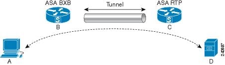
In this example the BXB and RTP networks are connected through a secure LAN-to-LAN tunnel by a pair of security appliances. A PC in the BXB network is executing an FTP transfer from a server in the RTP network through the secure tunnel. In this scenario, assume that for some reason the tunnel drops after the PC has logged into the server and started the transfer. Although the tunnel is be reestablished since the data is still attempting to flow, the FTP transfer will not complete. The user must terminate the transfer and start over by logging back into the server. However, if persistent IPsec tunnel flows is enabled, as long as the tunnel is recreated within the timeout interval, the data continues to flow successfully through the new tunnel because the security appliances retain the history (state information) for this flow.
Scenario
The following sections describe the data flow situations for a dropped and recovered tunnel, first with the persistent IPsec tunneled flows feature disabled, then with the feature enabled. In both of these cases, see the preceding figure for an illustration of the network. In this illustration:
- Flow B-C defines the tunnel and carries the encrypted ESP data.
- Flow A-D is the TCP connection for the FTP transfer and traverses the tunnel defined by flow B-C. This flow also contains state information used by the firewall to inspect the TCP/FTP flow. The state information is vital and is constantly updated by the firewall as the transfer progresses.NoteThe reverse flows in each direction are omitted for simplicity.
Disabled Persistent IPsec Tunneled Flows
When the LAN-2-LAN tunnel drops, both flow A-D and flow B-C and any state information belonging to them are deleted. Subsequently, the tunnel is reestablished, and flow B-C is recreated and is able to resume carrying tunneled data. But the TCP/FTP flow A-D runs into trouble. Because the state information describing the flow up to this point in the FTP transfer has been deleted, the stateful firewall blocks the in-flight FTP data and rejects the flow A-D creation. Having lost the history of this flow ever existing, the firewall treats the FTP transfer as stray TCP packets and drops them. This is the default behavior.
Enabled Persistent IPsec Tunneled Flows
With the persistent IPsec tunneled flows feature enabled, as long as the tunnel is recreated within the timeout window, data continues flowing successfully because the ASA still has access to the state information in flow A-D.
With this feature enabled, the ASA treats the flows independently. This means that flow A-D is not deleted when the tunnel defined by flow B-C is dropped. The ASA preserves and resumes stateful (TCP) tunneled flows. All other flows are dropped and must reestablish on the new tunnel. This does not weaken the security policy for tunneled flows, because the ASA drops any packets arriving on flow A-D while the tunnel is down.
Tunneled TCP flows are not dropped, so they rely on the TCP timeout for cleanup. However, if the timeout is disabled for a particular tunneled flow, that flow remains in the system until being cleared manually or by other means (for example, by a TCP RST from the peer).
Configure Persistent IPsec Tunneled Flows Using CLI
Configuration Example
Troubleshooting Persistent IPsec Tunneled Flows
Both the show asp table and the show conn commands can be useful in troubleshooting issues with persistent IPsec tunneled flows.
Is the Persistent IPsec Tunneled Flows Feature Enabled?
To see whether a particular tunnel has this feature enabled, look at the VPN context associated with the tunnel using the show asp table command. The show asp table vpn-context command displays a “+PRESERVE” flag for each context that maintains stateful flows after the tunnel drops, as shown in the following example (bolding added for legibility):
hostname(config)# show asp table vpn-context
VPN CTX=0x0005FF54, Ptr=0x6DE62DA0, DECR+ESP+PRESERVE, UP, pk=0000000000, rk=0000000000, gc=0
VPN CTX=0x0005B234, Ptr=0x6DE635E0, ENCR+ESP+PRESERVE, UP, pk=0000000000, rk=0000000000, gc=0

---------------------------------------------------------------------------

hostname(config)# show asp table vpn-context detail

VPN CTX  = 0x0005FF54

Peer IP  = ASA_Private
Pointer  = 0x6DE62DA0
State    = UP
Flags    = DECR+ESP+PRESERVE
SA       = 0x001659BF
SPI      = 0xB326496C
Group    = 0
Pkts     = 0
Bad Pkts = 0
Bad SPI  = 0
Spoof    = 0
Bad Crypto = 0
Rekey Pkt  = 0
Rekey Call = 0

VPN CTX  = 0x0005B234

Peer IP  = ASA_Private
Pointer  = 0x6DE635E0
State    = UP
Flags    = ENCR+ESP+PRESERVE
SA       = 0x0017988D
SPI      = 0x9AA50F43
Group    = 0
Pkts     = 0
Bad Pkts = 0
Bad SPI  = 0
Spoof    = 0
Bad Crypto = 0
Rekey Pkt  = 0
Rekey Call = 0
hostname(config)#
Configuration and Restrictions
This configuration option is subject to the same CLI configuration restrictions as other sysopt VPN CLI.
Locating Orphaned Flows
If a LAN-to-LAN/Network-Extension-Mode tunnel drops and does not recover before the timeout, there might be a number of orphaned tunnel flows. These flows are not torn down as a result of the tunnel going down, but all the data attempting to flow through them is dropped. To see these flows, use the show conn command, as in the following examples (bolding added for emphasis and to show user input):
asa2(config)# show conn detail
9 in use, 14 most used
Flags: A - awaiting inside ACK to SYN, a - awaiting outside ACK to SYN,
       B - initial SYN from outside, C - CTIQBE media, D - DNS, d - dump,
       E - outside back connection, F - outside FIN, f - inside FIN,
       G - group, g - MGCP, H - H.323, h - H.225.0, I - inbound data,
       i - incomplete, J - GTP, j - GTP data, K - GTP t3-response
       k - Skinny media, M - SMTP data, m - SIP media, n - GUP
       O - outbound data, P - inside back connection, p - Phone-proxy TFTP connection,
       q - SQL*Net data, R - outside acknowledged FIN,
       R - UDP SUNRPC, r - inside acknowledged FIN, S - awaiting inside SYN,
       s - awaiting outside SYN, T - SIP, t - SIP transient, U - up,
       V - VPN orphan, W - WAAS,
       X - inspected by service module
The following example shows sample output from the show conn command when an orphan flow exists, as indicated by the V flag:
hostname# show conn
16 in use, 19 most used
TCP out 192.168.110.251:7393 in 192.168.150.252:21 idle 0:00:00 bytes 1048 flags UOVB
TCP out 192.168.110.251:21137 in 192.168.150.252:21 idle bytes 1048 flags UIOB
To limit the report to those connections that have orphan flows, add the vpn_orphan option to the show conn state command, as in the following example:
hostname# show conn state vpn_orphan
14 in use, 19 most used
TCP out 192.168.110.251:7393 in 192.168.150.252:5013 idle 0:00:00 bytes 2841019 flags UOVB
评论